This is an account of my first look at another member of the XIAO family of tiny development boards from Seeed Studio, the XIAO ESP32C3. There's no big project here, I just wanted to compile and upload a few simple projects from the PlatformIO and Arduino IDEs. I also wanted to look at MicroPython on the XIAO.
The source code for all the C++ projects is made available in a single GitHub repository. Some care was taken to set up each project in a way that both PlatformIO and the Arduino IDE can use the same source code. The repository notes explain how that was done. The repository does not contain the example MicroPython script presented in this post. In keeping with the use of the Arduino-ESP32, two example projects which do the same thing as the MicroPython code are included in the repository. These are not discussed at all in this post.
This is a very personal examination of the XIAO ESP32C3. It was the first time I used ESP32-C3 based development board, but it is not my first project with PlatformIO, the Arduino IDE, and MicroPython. While I go into excruciating details where I was doing things for the first time, instructions for the rank beginner are not given. In particular there is nothing about installing the PlatformIO or Arduino IDE. There are numerous tutorials for beginners including the Espressif Installing Guide in the Arduino-ESP32 documentation which seems good with respect to the Arduino IDE, but amounts to providing a link to PlatfomrIO's own getting started guide. The screen captures shown below were done either in the Arduino IDE version 2.0.3 for Linux or in the PlatformIO IDE 2.4.0 extension of VSCodium (version 1.75.1) which "is a community-driven, freely-licensed binary distribution of Microsoft’s editor VS Code."
Table of Content
- Disclosure
- Tiny, Cute and Markedly Different
- A Rose is a Rose...
- Bootloader, Buttons and Bows
- Where is the Board?
- A Do Nothing PlatformIO Project
- Doin' Nothin' in the Arduino IDE
- Pin Numbers and Names
- At Last, the XIAO ESP32C3 Blinks
- Button Controlled LED
- Web Controlled LED
- Bluetooth Controlled LED
- MicroPython: REPL Controlled LED
- MicroPython: Web Controlled LED
- Uncurated Bibliography and Concluding Thoughts
Disclosure

 It is only right to disclose that I was given two XIAO ESP32C3 boards along with a XIAO nRF52840 Sense and a XIAO starter kit by Seeed Studio. Click on the image of the invoice on the right for details. The understanding was that Seeed Studio hoped that I would write a post about some of these products along the lines of my Overview of the SAMD21 Arm Cortex-M0+ Based Seeed Studio XIAO, but that there was no obligation, nor was a time line imposed. That's good because the package arrived five months ago, but I was so occupied elsewhere that I opened the first of the platic bags containing an ESP32C3 only on the 20th of February. As I write this, I assume that my contact at Seeed Studio must have given up hope, as he had the package send express by DHL back in October of last year!
If trying to judge how much I am beholden "to the man", take into consideration that there was no payment from Seeed Studio and that these notes and future posts have not and will not be submitted to Seeed Studio before being published. Besides, all I really do is describe how I go about doing things for my own use and I publish some of my notes in the hope that others may find the information useful. So this post is not a recommendation about various products because I simply do not have enough knowledge or experience to make judgments about the relative merits of the numerous devices that are available from many vendors. Now is a good time to repeat that I do not claim any expertise about the subject matter covered in this post or any other post on this site.
With that out of the way, let me add that I purchased another two XIAO ESP32C3 from Seeed Studio as soon as they became available again in late December 2022 even if I had no experience with them. When Seeed Studio offered low shipping rates for these cheap ($5 US) devices with attractive specifications, I jumped at the chance to get them, along with a couple of XIAO nRF52840, especially given the supply issues that have been plaguing the markets for electronic enthusiasts in the last few years. At the same time, I also purchased a similar number of WEMOS W600-PICO development boards which is based on another Wi-Fi enabled microcontroller. Blame that purchase, in part, for the delay into looking at the ESP32C3. More accurately, I made an error in my initial look at the W600-PICO that I felt was so egregious that my priority was to rewrite the whole thing as quickly as possible. The similarities and differences are interesting enough that I may write a comparison of the two boards in the future. Almost sixteen months after writing that last line, I haven't fulfilled that half promise. On the other hand, there is a review of some sub-par Super Mini ESP32-C3 boards first published in May and a recent look at the XIAO ESP32C6 which I have dubbed the big brother (2024-07-12).
Tiny, Cute and Markedly Different
The XIAO ESP32C3 by Seeed Studio is the fifth and latest addition to the Seeed Studio XIAO Series of diminutive development boards. As the name implies it is based on the ESP32-C3 microcontroller from Espressif which some, Elliot Williams at Hackaday and digiblurDIY notably, have touted as a replacement for the ESP8266. The ESP32-C3 is a departure for Espressif because it has a RISC-V processor instead of an Xtensa L106 processor. It is also a departure for the XIAO series since this is the first member that is not based on an ARM Cortex processor.
Because this is a first look the processor and development board will not be described in much detail. Let's just say that the RISC-V processor is single core and runs at 160 MHz. It has wireless connectivity: Wi-Fi (IEEE 802.11 b/g/n; 2.4 GHz; HT20/40; up to 150 Mbps) and Bluetooth LE (v5.0). Nominally it has two 12-bit ADC (analog to digital converters) available on 6 channels but one of these converters does not function properly as explained in the next section. There's also a full complement of digital interfaces including three SPI, two UART, one I²C and one I²S. As for storage, there is 400 Kbytes of static RAM, 284 Kbytes of ROM and 8Kbytes of static ram on the real-time clock. The chip used in the XIAO ESP32C3, the ESP32-C3FN4, comes with 4 Mbytes of on-board flash memory. The list goes on of course (source).
A Rose is a Rose...
 While currently named Seeed Studio XIAO ESP32C3 (SKU 113991054), the board was initially released as the XIAO WiFi/BLE - EPS32C3 (source). Consequently, there may be libraries for the device that use the older name, but I suspect that this will be much rarer than in the case of the Seeeduino XIAO renamed Seeed Studio XIAO SAMD21 much later after its release.
Saying that the XIAO ESP32C3 belonged to the "XIAO family of tiny development boards" was redundant because, as I found out months ago, XIAO means small or tiny. In any case, the board conforms to the XIAO 18x22 mm form factor shown on the right. There are 14 pads along the edges of the board, three of which are dedicated to power and ground connections and the remaining 11 pins are I/O. Four of these pins have no predefined functions, while the remaining seven are used to provide three serial peripherals: UART, I²C and SPI. Below is the specific pin assignments for the XIAO ESP32C3.


The pin naming convention is not the same as with the XIAO SAMD21 which is a bit unfortunate. Maybe it would have been better to adopt a "gender neutral" naming convention such as P0 to P10 at the very start with the XIAO SAMD21, but that's with the benefit of hindsight, of course. The perfect match between pin name and pin number of the XIAO SAMD21 (i.e., where "An" is the name of pin number n) is not present here. That is not a problem because symbolic names instead of "magic numbers" should always be used.
Note the grayed out A3 pin name. This Arduino pin name has been removed from the board definition. Officially, only the first of two analog to digital controllers is deemed to work and, consequently, there are only three viable analog to digital I/O pins on the XIAO: A0, A1 and A2 (references: The Digital Controller of SAR ADC2 cannot work and the XIAO ESP32C3 Pinout diagram.
Because the ESP32C3 does not have an ARM Cortex microcontroller the connections at the back of the board are quite different from the other members of the XIAO family. The SWD debug interface is replaced with a JTAG interface. The four JTAG I/O pads connect to I/O pins already available on the edge connectors. The board also has battery connection pads as it can be powered from a battery and can charge the battery when powered from the USB connector or the 5 volt pin. The board has no power or user-controlled LEDS. The small red LED near the USB-C connector labelled CH is a charge indicator.
As with other members of the Seeed XIAO family, Adafruit has an equivalent product, the QT Py ESP32-C3 in its line-up of QT Py / XIAO development boards. At roughly twice the price of the Seeed model, it is based on the same the ESP32-C3FN4 SoC. It boasts a neo-pixel, an on-board antenna and on-board STEMMA QT connector parallel to the I²C pins which is somewhat compatible with the Seeed Grove connector. The QT Py does not have JTAG pads as far as I can make out. Furthermore components are mounted on both sides of the board so if the QT Py were to be soldered using its castellated pads, a cutout would have to be made on the larger board.
Bootloader, Buttons and Bows
 The XIAO has two normally open push buttons and one large bow. It's not really a bow of course, but it is an elegant, mat black, Wi-Fi and Bluetooth antenna. While very thin, it's area is almost twice that of the XIAO itself. The U.FL coaxial connector is very small, a bit fiddly and will probably not survive very many connections (the female connector on the antenna is rated for only 30 reconnections, see Hirose U.FL), so I will try to avoid disconnecting it.
There are two small push buttons at the bottom of the board along the edge opposite the USB-C connector. The one on the right is the reset button while the on the left is the boot mode button needed to put the board in bootloader mode. The reset button works as expected. It is a welcome addition compared to the bare pads of the XIAO SAMD21 which generated (warning! hyperbole about to be committed) half of the postings on the forum when that board was launched. The Seeed Wiki talks about the boot button and bootloader mode only in the context of reflashing the factory firmware, something I have not done nor see the need to do. Nevertheless, that boot button very useful. The sequence of button presses and releases to get into bootloader mode is pretty common.
- Press and keep depressed the reset button.
- Press and keep depressed the boot button.
- Release the reset button.
- Release the boot button.
Another way of putting the board in bootloader mode is described in the Wiki.
- Remove power to the board, usually by disconnecting the USB cable.
- Press and keep depressed the boot button.
- Apply power to the board, usually by connecting the USB cable.
- Release the boot button.
Be deliberate about these steps, there is no rush. Once the sequence is completed, the board will be in bootloader mode waiting for new firmware. Uploading should now work. Remember that after the upload is finished, the board remains in bootloader mode and the reset button must be pressed and released to return the board to normal mode where it will execute the newly uploaded firmware.
If I were a bit more careful, there would hardly be any need to put the XIAO into bootloader mode. The following uploading error occurs regularly in PlatformIO.
Putting the XIAO in bootloader mode is a possible solution, but usually that is not necessary. I carelessly let windows accumulate, piled one on top of the other, at the bottom of the VSCode window as I push the build, upload, and terminal buttons in the PlatformIO toolbar. Then I'll fail to spot a spinner in the stack indicating that a terminal is waiting for some input, which invariably interferes with an upload. If every window was closed properly, most times an upload will go through without a problem.
Where is the Board?
Enough with the introduction, it's time to play with the board. Because it has a USB-C port used to supply current and as a programming interface just like the XIAO SAMD21, I assumed that it would show up as terminal (TTY) device. To find it, I started printing the kernel ring buffer on my Linux Mint desktop machine with the dmesg -w command. The -w (or --follow) flag means that utility will not terminate once it has printed all previous messages but will remain active and will print new messages as they come in. I waited until dmesg had finished printing all the old kernel messages and then I plugged in the USB cable from the XIAO to a USB 2 port on my Linux Mint desktop.
As usual the CtrlC keyboard combination halts execution of the process. The USB vendor and product ID were new values that I had not encountered before. When listing all USB devices, not much information is shown, but it is possible to get much more information by explicitely asking for it.
Most of this information is not particularly important at this point, but it is nice to see that the USB port has a serial number. Investigating by looking up the serial numbers of the four XIAO that I have in a Media Access Control or MAC address database, it looks very much as if that serial number is a MAC address assigned by Espressif to each ESP32-C3 microcontroller produced. The fact that the USB connection has a unique identifier can be very useful when trying to set up udev rules for specific devices that are connected to a USB port.
With all that said, the XIAO ESP32C3 shows up as a ttyACMxx device just like the XIAO SAMD21. At this point, I connected directly to the device with the old, dependable "Call up another system" cu command.
This output looks like the firmware could be a factory test to ensure that the board is functioning properly. Everything is failing which makes sense as there is no testing fixture connected to the board. Whatever this firmware is, it will be erased in the next steps. I presume that it could be restored by flashing the Seeed Studio XIAO ESP32C3 Factory firmware available from the Seeed Studio Wiki. Note how the linked file is named ESP32-C3_RFTest... so that sort of makes sense.
It did not matter if the baud was set to 115200, 9600 or 500000 or probably anything else when connecting to the board with the cu . Just like the XIAO SAMD21, the USB data lines are connected directly to the microcontroller which has a built-in USB serial controller with a CDC-ACM virtual serial port which is USB 2.0 compliant and capable of 12 Mbits/s transfer speeds (Source ESP32C3 Series Datasheet, Version 1.4 pp 25).
A Do Nothing PlatformIO Project
Check if platform Espressif 32 is already installed in PlatformIO or PIO for short. If it is, make sure it is up to date. Do that by clicking on the Platforms icon in the PIO Home side bar, clicking on the Installed tab at the top of the window, and by entering Espressif in the Filter platforms by name... box at the top of the list of installed platforms.

If the Espressif 32 platform is installed, it will be displayed along with the currently installed version number. To check if it is up to date, click on the Updates tab at the top and enter Espressif in the Filter platforms by name... box once again.

If Espressif 32 is not shown as above, then the installed version is the most recent. Otherwise, the platform is displayed and clicking on the button will install the newest version.
If the platform is not installed, there is nothing much to do because the newest version will be installed automatically when a new project using the XIAO ESP32C3 is created in the next step.
I created a new project by first clicking on the Home icon in the PIO Home and then clicking on + New Project under Quick Access.

Then it's a matter of filling in the fields in the project wizard setup page.

There are so many supported boards in PIO, it is best to start typing some words that will narrow down the search. It will be easy to select the XIAO ESP32C3 after entering xiao into the Board: drop down edit box. Note that I did not use the default location and instead let PIO create a project directory named FirstRun in a directory called ~/Documents/PlatformIO/Projects/esp32c3. When I clicked PIO automatically created the project directory and subdirectories, a do-nothing sketch main.cpp in the src subdirectory.

Click on the Explorer icon at the left edge of VS-Code to see the project directory and open the src subdirectory and click on the main.cpp file name to see its content in the editor. PIO also created a default platformi.ini configuration file in the project directory.
The upload and monitor ports are not specified so adjustments may be needed. Thankfully, the latest versions of PlatformIO have better board definitions and I have found that PIO finds the XIAO /dev/ttyACM0 which will be assigned to the XIAO if it is the only USB communication device connected to the desktop. If other USB CDC devices are connected to the computer, then it may be necessary to specify the serial port in the configuration file. As an example, three serial devices are connected to the desktop.
The last two are ESP32-C3 devices and the last one plugged in is the one I want to use. So here is the platformio.ini file to do that.
This worked as I compiled and uploaded the "do nothing" binary without interfering with the other serial devices.
The emphasis shown in the listing above was added by me.
Doin' Nothin' in the Arduino IDE
The recently released version 2 of the Arduino IDE represented a major improvement. While PlatformIO remains a better choice for me, I think the new Arduino IDE is good. Actually, the Arduino IDE has better management of example sketches in my opinion which could be an important especially for beginners. Of course, it is possible to use both environements. As a matter of fact, both are installed on my desktop computer and both get used. Consequently, it seemed appropriate to upload a "do nothing" sketch using the Arduino IDE to check if there are connection problems. To do this, I used the latest, self-contained, 2.3.2 Linux 64-bit appImage of the IDE. Then it was necessary to added support for third-party ESP32 microcontrollers within the IDE. That is a two-step procedure.
- Add
arduino-esp32package information which is done by entering the URLhttps://espressif.github.io/arduino-esp32/package_esp32_index.jsonin theAdditional boards manager URLs:list in theSettingstab of the applicationPreferencesfound in theFilemenu. - Install the package using the IDE top menu
Tools » Board » Boards Manager..., typeesp32in the search box, select the latest version ofesp32and then click on the INSTALL button. Currently the latest version is 3.0.2.
It is simpler than described, details can be found under Software setup in the Getting Started Seeed Wiki.
Once the XIAO was plugged into the USB port of the desktop computer, it was not correctly identified.

By clicking the Select other board and port... option in the drop down menu, I was able to select the XIAO ESP32C3 and the correct port /dev/ttyACM0 from the list.

To find the correct board among the very long list, I entered "xiao" in the BOARDS search box, and then clicked on XIAO_ESP32C3 and selected the correct port before clicking on the OK button. From then on, it was easy to compile the do-nothing sketch and upload the generated binary successfully. One can see a part of the Output window below the Tools which shows that 100% of the binary was uploaded and that the data was verified. The following bit was also shown in the output window but it has scrolled out of view by the end.
Pin Numbers and Names
Instead of the classic "Hello World!" program, I decided that the first sketch uploaded to the XIAO would print out the pin assignment as defined in pins_arduino.h found in the Arduino Espressif32 package in the following directory: ~/.platformio/packages/framework-arduinoespressif32/variants/XIAO_ESP32C3/ or ~/.arduino15/packages/esp32/hardware/esp32/3.0.2/variants/XIAO_ESP32C3/ if using Arduino IDE.
Note that the board identifier macro, ARDUINO_XIAO_ESP32C3, is not defined in the pins_arduino.h. It is just something useful to know when wanting to create programs that accommodate slight differences between different boards. Since there is no longer a fourth analogue pin (A3), it might be better to assign SS to I/O pin 5 to avoid a conflict between the SPI and UART peripherals. This is what is done on the XIAO ESP32C6 and may be worth investigating.
The code for the firmware that printed the above results to the serial monitor can be found here: 01_pin_names. The code is rather boring, just a bunch of print statements, one for each of the line of output seen above. Even the setup() function is very simple.
Those first two lines are typical for all sketches that send text to the serial monitor running on XIAO series boards. They would not work with other development boards that have an on-board USB-serial adapter (CH340, CP9012, FT232, etc) or require an external one. With those boards it is necessary to set the baud of the serial port as a parameter as in Serial.begin(115200). With the ESP32 XIAOs, Serial is an instance of the HWCDC class. I think that stands for hardware (USB) CDC or USB Communications Device Class.
Looking at void HWCDC::begin(unsigned long baud) function found in ~/.platformio/packages/framework-arduinoespressif32/cores/esp32/HWCDC.cpp it is clear that baud could be anything; indeed the default value is 0 and the parameter is actually ignored in the method. So Serial.begin(115200) would work just as well and it would be compatible with other boards. However one has to be careful. It takes time for the native USB connection to be established with the desktop. However I have found that the if(Serial) test does not work with the ESP32.
The "Starting setup()" line will never be displayed on the serial monitor. Furthermore, that sketch will hang, remaining in the while loop indefinitely if the board is not connected to a computer. For that reason, I prefer the simple 2 second delay which seems sufficient for the establishing a USB connection when the board is connected to a PC and does not hang when it is not.
At Last, the XIAO ESP32C3 Blinks
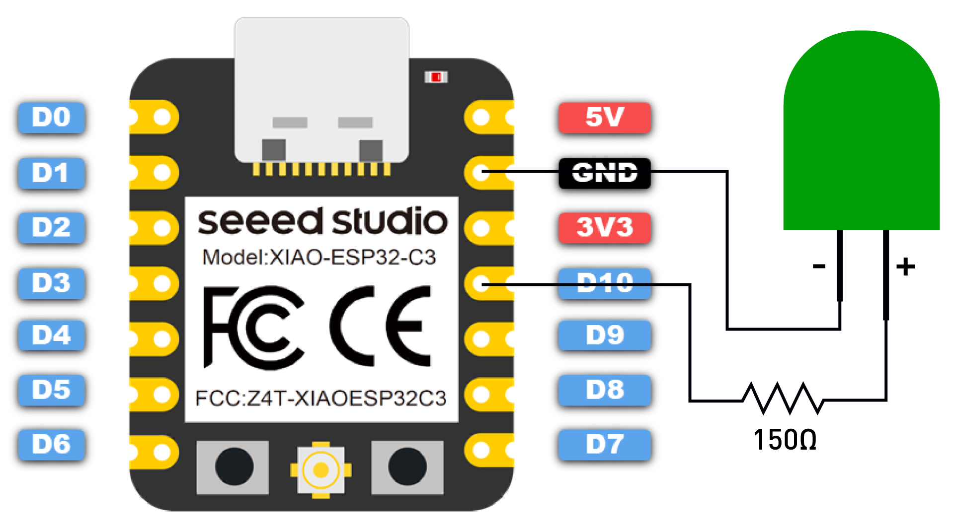
The obligatory blink sketch is usually the first program uploaded to a new microcontroller. It is the third sketch here (don't forget the do-nothing sketch). I assumed that impatient readers would want to run something on the XIAO ESP32C3 as quickly as possible before hunting for an LED and a resistor given that the XIAO has no on-board user LED. The Seeed Studio Wiki already contains a blink sketch in Getting Started with Seeed Studio XIAO ESP32C3, complete with wiring diagram, but I have modified it slightly because it is hard to show a blinking LED on a static Web page. This version of the sketch prints the state of the LED out to the serial port as it toggles it on and off.
Here is the serial output of the program which can be obtained here: 02_blink_led.
The source code on GitHub is slightly different from what is shown where it is assumed that setting the I/O pin connected to the LED to HIGH will turn it on. That is correct given the way the LED is wired. However, on all the XIAO boards that have a built-in LED and many other development boards with an on-board LED, the latter's anode is connected to GND and the cathode is connected to an I/O pin which must be set LOW to turn the LED on. That's why there is a ledOn constant to accommodate either ways of connected an LED to an I/O pin. And that also why the on and off times are asymetric to ascertain if it's a LOW or HIGH signal that turns the LED on.
Button Controlled LED
 Let's control the LED with a push button. The on-board boot push button could be used, but my test setup is not ideal making it hard to reach the button. I prefer connecting another normally open push button connected to ground and D1 instead. Being lazy and hoping for some free publicity to the many thousands who will be reading this post, my own button library will be used. Since it is available on GitHub, a simple
 lib_deps directive in the platformio.ini configuration file will take care of the dependency. For those using the Arduino IDE, the mdPushButton in included in the libraries directory so that there is nothing to install in the IDE.
Here is the listing, which is nothing more than the basic button example from the mdPushButton library with the addition of the toggleLed() function.
I was very pleased to see that my push button library worked with the ESP32-C3 without any tweaking. In other words, the program works as expected, the LED is toggled on or off with each single press of the added button. Long presses and two or more successive button presses done in quick succession do not toggle the LED, but they are reported to the serial monitor.
The version available for download at 03_button_led will again contain a ledOn constant to deal with LED connected to ground via their anode or cathode. This involves a slight change to the toogleLed() function.
Note how the state of the LED is never saved in the sketch. Instead the value of the I/O pin connected to the LED is read. This has worked with all the microcontrollers I have used, but it is not assured that this will always be the case. Reading a digital pin that has been explicitely set to ouput mode could be an undefined operation with some devices.
Web Controlled LED
The wireless connectivity of the ESP32-C3 is very appealing for those interested in home automation. Here is a very simple example of controlling an LED with a web page. Of course in practice, a relay controlling a lamp or other device could be used instead of an LED.

As before, it is hard to show the state of a LED in a web page, so here is the serial output of the XIAO ESP32C3 as a client web browser connects to the web server and then as the button on the web page is clicked.
I will not go into the detail of the source code (available here: 04_web_led) especially as it is an example that can be readily found on the Web. Though let's mention that it uses the WiFiServer class defined in WiFi.h which is part of the ESP32 Arduino core. Even if this example is very popular, I find it difficult to follow and extend.
The AsyncWebServer found in ESPAsyncWebServer is, in my opinion, preferable to WiFiServer. There is a simple example in 05_async_web_led. In contrast to the first version, the second version makes use of the template processing capabilities of the ESPAsyncWebServer library, which does simplify the code. However that just the tip of the iceberg. It is relatively easy to handle multiple clients with the async library. Furthermore, it supports ajax, websockets and sse which are technologies that can be used to update the web interface when the state of the LED is modified with a button, for example. This is an important, indeed necessary, feature of an IoT device Web interface. An indication of what is involved can be obtained by looking at the series of posts about A Wi-Fi Switch for Domoticz using a XIAO ESP32C3.
I should point out that the me-no-dev version of ESPAsyncWebServer does present some challenges although mos were mitigated when version 1.2.4 was released a month ago. Since then, there is no need to load a development version of the library meaning that the following line lib_deps = me-no-dev/ESP Async WebServer@^1.2.4 in platformio.ini takes care of all dependencies when compiling the 05_async_web_led project in PlatformIO. The project should compile correctly in the Arduino IDE because the libraries directory contains the latest version from me-no-dev. For this to work, an older version of ESPAsyncWebServer or any fork must not have been installed manually or with the library manager.
I found two forks of the me-no-dev ESPAsyncWebServer library in the Arduino IDE Library manager. These were ESPAsyncWebServer (3.1.0) by lacamera and ESPAsyncWebSrv (1.2.7) by dvarrell 1.2.7. However in both cases, the following error occured when compiling the project.
I know that this was solved as far back as February 2023, but neither fork incorporated the correction. Even last week someone complained in the me-no-dev repository about this error Problem resolved ? "Arduino\libraries\ESPAsyncWebSrv\src\WebAuthentication.cpp:74:3: error: 'mbedtls_md5_starts_ret' was not declared in this scope; did you mean 'mbedtls_md5_starts'?". Both me-no-dev and lizardb0y explained that the solution was to use version 1.2.4 of the me-no-dev library. Nevertheless, others continued to complain that the forks of the library still had errors and someone even showed how to patch one of the forks. This is puzzling to me. I can't see why one would expect that errors in forks should be corrected by the developer of the original library.
Bluetooth Controlled LED
Unlike the ESP8266, the ESP32-C3 has Bluetooth® Low Energy (BLE) capabilities. My knowledge in this area is so limited (one tiny post: BLE Beacons with Tasmota32 - Proof of Concept) that I do not want to say much. Let's just say that I was able to simplify an example from Shahzada Fahad (Engr), XIAO ESP32C3 Bluetooth Tutorial, Range test, and Home Automation to control the LED connected to the XIAO ESP32C3.
The sketch uses the ArduinoBLE library, which is added as a dependency in the ble_led platformio.ini configuration file.
The source is almost comprehensible.
On uploading the firmware to the XIAO it seems to stop once the setup function is completed.
But that is not the case, the XIAO is simply waiting for a connection. I opted to use an Android tablet to continue with this example. Shahzada Fahad used nRF Connect for Mobile and it does work. However, I will be showing the use of LightBlue below. There are IOS versions of both of these programs, nRF Connect and LightBlue, but I have not tried either of those.
Once installed from Google Play Store, start LightBlue. There is no need to pair the XIAO to the phone or tablet, LightBlue will take care of this. Click on the thumbnails on the right to see a full-sized version of the screen capture.
| Chances are LightBlue will ask permission to access the location of the device on which the app is running and chances are that it will have to be given. You could always refuse to see the reason why the app asks for the permission. |  |
If the Bluetooth radio was not turned on, then the app will ask for permission to turn it on. Of course refusing to do that will bring this exercise to an abrupt end. (Refusers is an "interesting" spelling error). |
 |
| Press on the button to get beyond the welcome screen of the app. |  |
| In the list of nearby Bluetooth devices, press on the CONNECT button beside "HOME Automation" |  |
LightBlue will show information about the BLE device on the XIAO in detail. Scroll down to the end of that page. |
 |
Press on the Readable, Writeable entry at the end of the GENERIC ATTRIBUTE |
 |
| The properties and other data about the generic attribute will be displayed, and again it was necessary to scroll down to get to the important field. |  |
Write 0 or 1 in the WRITTEN&npbs;VALUES Hex data... field and then press on the button to send it back to the XIAO. It will turn the LED off or on as desired. |
 |
| Note the hexadecimal keyboard used to enter the attribute value. |  |
| Once a value is written, it is added to a list of attribute values previously send back to the XIAO. |  |
The sketch shows the received values in the serial monitor. It also reports when an invalid value is received.
While it is not easy to compile this project in the Arduino IDE, it can be done as explained in the ble_led.ino file in 06_ble_led. Consequently, I decided to create a second version of this project using the BLE libraries that are included in the ESP32 Arduino core. That avoids name conflicts and 07_ble_led compiles just as easily in the Arduino IDE as in PlatformIO. Again one could use nrfConnect or LightBlue to connect to the XIAO via Bluetooth to control the LED. This second version can use predefined UUID for the characteristic and service. These do make the use of the Android clients somewhat more intuitive. No matter which type of UUID is used, the LED is controlled with a Bluetooth client such as Light Blue in exactly the same fashion as the version based on ArduinoBLE.
MicroPython: REPL Controlled LED
Following the instructions at MicroPython ESP32-C3 with USB, I downloaded the latest v1.19.1 release of MicroPyton into a directory in my desktop machine. It was a matter of using esptool to upload the binary to the XIAO ESP32C3. I knew that there were many copies of that utility on my machine, so a search in the PlatformIO packages directory to find the most recent version seemed advisable.
A check of the esptool GitHub repository showed that version 4.5 was indeed the latest release. Since the binary is not on my search path, I created an alias, to avoid typing a very long command and tested it by displaying the esptool version and then using it to view some information about the ESP32-C3 on the XIAO.
chip_id. After enough resets into bootloader mode, I could get the flash_id but never the chip_id. It turns out that PlatformIO had some control over the serial port, even if it looked as if I had stopped the serial monitor. Once I unloaded the PIO project that was open, everything worked perfectly.
To simplify things, I made the directory where the firmware was uploaded the current working directory and checked the firmware's name. Note that a upy- prefix had been added to the name when the file was downloaded to make it easier to identify. Uploading the micropython firmware according to the instructions was a breeze.
Even if esptool says it reset the XIAO, it didn't because there is no RST connection through the USB port. So activate the XIAO reset button to exit bootloader mode.
Once again I used cu to connect to the MicroPython REPL. Nothing seemed to be happening until I pressed the Enter key at which point the REPL prompt >>> appeared. A keyboard combination CtrlD initiated a soft reset which in turn displayed the initial MicroPython screen.
Let's turn on and off the LED connection to I/O pin 10. Note the GPIO pin number is used in MicroPython, not an alias such as D10.
Of course that's not very practical, but with the XIAO Wi-Fi capabilities it is relatively easy to control the LED with a web server built with MicroPython.
MicroPython: Web Controlled LED
For my next trick, I decided to just modify an example web server W600-PICO. I used the same Thonny IDE as before, the only difference was that I had to configure the interpreter to use a different port: USB JTAG/serial debug unit (/dev/ttyACMO). The firmware can only serve two web pages, the default page at http://192.168.1.59/ and a 404 error page whenever a non-existent page is requested or an unknown request is made.


To toggle the state of the LED, click on the button. A request, http://192.168.1.59/?led=toggle, will be sent by the client web browser back to the Web server which will then act on receipt of that request to change the state of the LED. The Web server code is spread over three files. First there is a secrets.py file that contains the Wi-Fi network credentials and the fixed IP address to be assigned to the Web server. Here is a template for that file, which will have to be modified in accordance with the local network.
The httpresonses.py module has two functions. The first returns an HTTP response header whose content will be different depending on whether a 404 error HTML page or the index HTML page will be sent. The second function returns the full text of the HTML page to be displayed by the client web browser. Its content depends on whether it is a 404 error page or the index page. The state of the LED is passed onto this second function so that it displays the state correctly.
Here is the main.py module which is executed automatically whenever the XIAO is booted.
Notice how the LED is first turned on for a two seconds at the beginning, and then flashed 10 times just after the web server starts accepting connections. That helped in figuring out what was happening when starting the application. It turns out that the XIAO draws so little power when the web server is waiting for a client connection that the power bank I was using to test the firmware without a connection would disconnect the XIAO entirely.
Finally here is the serial output as displayed in the REPL.
That unusual Quit button is just a quick way to return to the REPL.
The source code for this MicroPython script is not included in the GitHub repository, but it can be downloaded from this site: upy_web_led.zip.
Uncurated Bibliography and Concluding Thoughts
Here is an uncurated bibliography, meaning here are links to various sources that I have consulted in the last few days while writing this post. I am sure there are other sources that would be just as informative if not more than what I found. Any suggestions would be welcome.
- Seeed Studio:
- PlatformIO: Board documentation
- Wiki: Getting Started with Seeed Studio XIAO ESP32C3.
- Forum: Micropythhon support for XIAO ESP32C3 and All XIAO ESP32C3 topics.
- Espressif Systems:
- ESP32-C3 Series Datasheet, Version 1.7.
- ESP32-C3 Technical Reference Manual, Version 1.1
- ESP32-C3 Series SoC Errata
- hackster.io: XIAO ESP32C3 Projects
- Shahzada Fahad (Engr):
- XIAO ESP32C3 Getting started tutorial with Projects, ESP32 C3 with accompanying video.
- XIAO ESP32C3 Bluetooth Tutorial, Range test, and Home Automation with accompanying video.
- techiesms: Getting Started with XIAO ESP32 C3 (video).
- PlastiBots: SEEED XIAO ESP32C3 Review and Demo of ESP-NOW Feature (video).
- Algobotics: Testing The Amazing ! new Xiao Wifi ( esp32-c3 ) (video).
- digiblurDIY: ESP32-C3 First Look - The Next ESP8266? (video).
- Adafruit: QT Py ESP32-C3 WiFi Dev Board.
Is it an ESP8266 replacement? It does not look as if Espressif is planning to drop the older device. The device still shows up in its product line and, this very month of February 2023, the Hardware Design Guidelines for the ESP8266 have been updated. However looking at pricing, the future is not so clear. Here are the listing from Mauser Canada for single core Espressif microcontrollers that were in stock on Feb. 26, 2023. All prices in Canadian dollars.
| part | price ($) | SPI Flash (MB) | PSRAM (MB) | Notes |
|---|---|---|---|---|
| ESP8266EX | 2.21 | 0 | 0 | |
| ESP8285 | 2.48 | 1 | 0 | Used in Sonoff Basic |
| ESP8285 | 1.66 | 2 | 0 | |
| ESP32-C3FN4 | 1.90 | 4 | 0 | Used in XIAO ESP32C3 |
| ESP32-S2FN4R2 | 2.37 | 4 | 2 | Xtensa LX7 core |
These prices do not seem to make much sense when compared to the comparative capabilities of the controllers. Perhaps the surprisingly high price of the older 8266/8285 parts has something to do with meeting the production demand for older devices. In the long run, demand for the ESP8266 may disappear as older products are removed from the markets and replaced with new designs based on newer chips.
This is just the opinion of an amateur, but the ESP32-C3 by Espressif is a very good SoC which is a better than ESP8266 as far as I can tell from my preliminary examination. It has more static RAM, much more flash memory, more analog input pins, a faster TCP stack, a built-in USB-to-serial peripheral (this is not native USB, so no HID capabilities) and so on.
The ESP32-C3 is not the first Risc-V microcontroller. I toyed with the Longan Nano and Wio Lite RISC-V back in March and April of 2020. However there is no real comparison from the amateur's point of view between the older boards. The Arduino framework for the ESP32-C3, which I believe is the work of Espressif, is much better than for the older board. It really feels as if one is programming for any ESP32 (aside from the single core restriction) when working with the ESP32-C3. This is probably an unfair judgment because I have not looked at the older boards since those first experiments.
As for the Seeed XIAO ESP32C3, again my first impressions are very positive. I believe this board can be seen as a replacement for the Wemos D1 Mini based on the ESP8266. It offers the same number of I/O pins as the bigger D1 mini (and even bigger nodeMCU ESP8266 boards), with the greater flexibility of the ESP32-C3. It was possible to install Tasmota for the ESP32-C3 on the XIAO and, after some difficulties with the installation, it was possible to integrate the XIAO ESP32C3 into my Domoticz based home automation system. I am looking forward to looking at improving some of my old projects, especially Domoticz Button, a light-weight physical interface to a home automation system based on Domoticz. It would be interesting to redo it in MicroPython to see if it could be made more "user-friendly".